Traffic Trax
Installation
The following
instructions outline the installation process for a standard doorway.
Inventory

Sample
Installation. Please note that the CAT5 line will be completely hidden
from view in the door frame.
·
Traffic Counter
Initial Layout and getting prepared before you
install.
·
Please read and make sure you
understand before
you begin this installation. Please call
(713) 532-1106
if you have any questions.
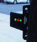
- Make sure the box is installed horizontally
and the red
and green lights are pointed into the store and the plastic lens is pointing
across the entry towards the reflective material or for wider entrances over
10 feet the included second black box.


- The top of the counter and the top of the reflective
material should be installed at 60 inches to remove counts from small children
running back and forth.) This will put the actual beams at 58 and ½ inches
and catches most adults and insures accuracy.
- The reflective strip is approximately 2 inches by 3 1/2
inches and should be mounted vertically on the door frame so the top of the 2
inch strip is exactly 60 inches high off the floor. Only a 1 inch
diameter circle is required to have solid alignment but we provide the extra
material to insure the best possible beam reflection. If you have extra
material over hanging on the door frame, trim this so it is neatly flush with
the edge and place the additional material on the opposite side of the cut
reflector on the frame.
- The traffic counter should be mounted on the hinge side
of the doorframe and part of the back of the counter should be exposed so you
can easily adjust the alignment screw with the provided 1/16 inch Allen wrench. Please notice the picture above displays the
counter and is mounted so that part of the device is exposed so you will have
access to the alignment adjusting set screw and the RJ-12 port and can
easily plug in the communication cable. Sometimes a metal door frame has
less than one inch of metal to mount the device and this is fine as long as
you can securely tighten the top and bottom screws through the mounting
bracket into the door frame securing the device. This is a line of
sight device and the only requirement is that the reflector and the counter
maintain clear visibility of one another.
- The wiring should be hidden inside the door frame above
the ceiling (if possible) or through wire mold or conduit, and
run to the customers existing designated TRAX PC. Do not run the wire over any lighting
boxes or electrical ballast boxes. And we have found that using push rods for
laying the cable makes this job very easy (these are available at Home Depot
for around 30-40 dollars and are a good investment for any ceiling or cable
running issue.
- The counter has a very good door chime located in the
Mux Box) that only goes off when a customer enters (not when they leave). The
Mux box should be installed on a PC in the sales area. The closer to the
sales area the better, and the easier the installation will be for you. We do
not recommend that you install the Mux Box in a server area because the
salespeople will not hear the chime and the server area is problematic because
techs have been know to disconnect the equipment not knowing what it was.
Also many times a server has a timeout function which stops counts from
getting to your web site.
- The Modified CAT5 line (three pair) is then connected with the pre-terminated
RJ-12 connection which plugs into any port on the Mux box (black the size of a
square cell phone).

- This also provides power to the counter at the front
door and a serial connection to the existing customers PC (Standard RS-232
Serial Connection).
- When completed always leave the loop back tester and
Allen wrench at the store in a TRAX file with the manuals so they can be
referred to in the future. Leave with store manager and ask that they save in
a safe permanent location.
- The standard traffic counter (installations at entrances
of 10 feet widths or less will have a reflective tape with a peel off back.
The top of this tape and the top of the counter should be placed at exactly 60
inches from the floor. The 2" reflective tape can be cut so it conforms
to any entrance. IE: an entrance with a one inch step frame at different
levels. A good tip is to not permanently secure the tape until the
counter has been aligned. Use a piece of scotch tape first then peel off
back of tape after you see the red light and two solid green lights and have
heard a beep when you pass your hand in front of the counter.
- If you must install the counter on a wall please know
that you will need to align the counter after the unit is installed. This can
easily be accomplished by shimming the angle to the proper alignment so that
you have two green lights and one red light.
- The system has the ability to have a four second delay
(counts a family of five as one count) or can count each person separately.
Most customers have us program the four second delay before we send the unit.
To test proper alignment after installation is complete hold you hand in front
of the counter so the two green lights go out. Then slowly move your hand
into the store. You will see the green lights flicker back on then the red
light will go off for four seconds then turn back on. You will also hear the
beeper make a short beep. This means that your counter has counted
one entry. The beep can be turned off and let the customer know that the
beeper only goes off when people enter, not when they exit.
- Please note that the counter can be either a USB or
RS-232 (9 Pin Serial) connection to the customers PC. We normally will
ship a 9 pin serial unit unless the customer has specified only a USB is
available on their PC. Then the counter is programmed accordingly before
it is sent to you.
- The final test to insure that the counter is perfect is
to #1 place your hand in front of the counter for two seconds (green lights
will turn off. #2. Move your hand slowly into the store (in the
direction of a customer entering). You will notice the green lights
flickering back on then the red light will go off for 4 seconds and turn back
on. You will also hear the beep from the Mux box. Your counter is
now aligned properly and will begin counting customers.
Please call 713-466-7177 or
713-466-4148 if you have any questions.
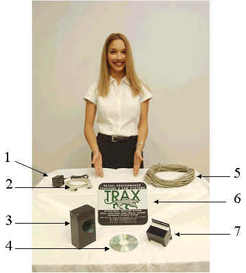
1. AC Adapter
Output: 7.5 Volt 300mA
2. 9 Pin Serial
Cable 6 ft. Or USB connection.
3. Serial
Interface MUX Box. Reduced to about the size of a cell phone.
4. Software
(installed by TRAX online) before or during installation
5. 125 ft.
Modified CAT
5 (three pair) Cable Terminated with RJ-12 (six wire/three pair)
connections
7. Beam Unit
Included is an accessory packet
containing the following. (Items Not Pictured)
1. 4 #10 x 1
3/16 Screws with Plastic Anchors
2. 1 Allen
Wrench 6 - 32
3. 1 Reflective
Strip Sticker 2 x 3 1/4
4. 9 Pin Serial
Loop Back Tester
Note: The Serial Interface
has three inputs. This device is designed to connect three individual entrances
to the same system. Each port performs the same function and are not beam unit
specific. In a standard one entry configuration the cable may be plugged into
any of the three.
Click Here to take a quick test to see if you are ready.
Sample Installation. Please note that the Modified CAT5 line will be completely hidden
from view in the door frame.
Please click the cat


