Visual Proof Initial Layout and getting prepared before you install. (please read and make sure you understand the first three paragraphs before you begin this installation. Please call (713) 532-1106 if you have any questions.
Please call 713-466-7177 or 713-466-4148 if you have any questions.
1. AC Adapter Output: 7.5 Volt 300mA
2. 9 Pin Serial Cable 6 ft. Or USB connection.
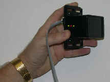
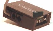
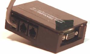
3. Serial Interface MUX Box. Reduced to about the size of a cell phone.
4. Software (installed by TRAX online) before or during installation
5. 125 ft. Modified CAT 5 (three pair) Cable Terminated with RJ-12 (six wire/three pair) connections
7. Beam Unit
Included is an accessory packet containing the following. (Items Not Pictured)
1. 4 #10 x 1 3/16 Screws with Plastic Anchors
2. 1 Allen Wrench 6 - 32
3. 1 Reflective Strip Sticker 2 x 3 1/4
4. 9 Pin Serial Loop Back Tester
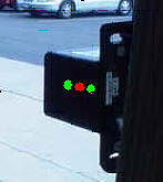
Note: The Serial Interface has three inputs. This device is designed to connect three individual entrances to the same system. Each port performs the same function and are not beam unit specific. In a standard one entry configuration the cable may be plugged into any of the three.
Please note that the Modified CAT5 line will be completely hidden from view in the door frame.
#2. The camera should be installed in the ceiling at a 75-90 degree angle from the front door and (most importantly) not directly pointing at the front door. This is important because
you do not want to be viewing the sun reflecting off windshields in the parking lot or sunlight off the concrete in front of the store outside.
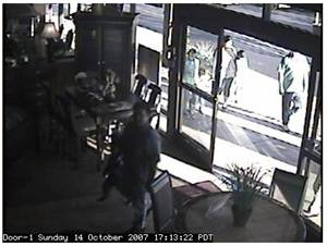
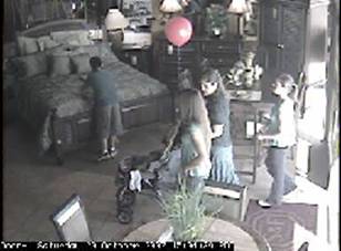
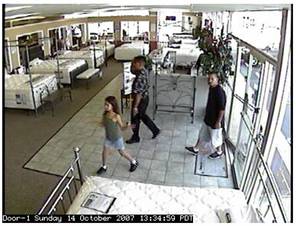
#3. Please confirm which way customers turn into the store (typically away from the sales area) and the camera should not be closer than 20-30 feet from the front door, (you need a full field of view of the entire entryway inside the store) The camera takes the picture 1.25 seconds after the customer walks in so we can see the entire family, so make sure you can still catch the really fast customers walking in at a trot.
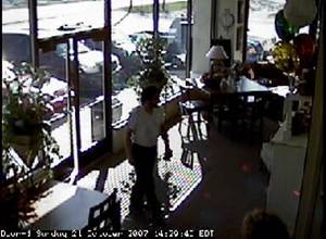
Sample of a poor installation. This is too close to the door. If the customer goes fast you will miss them completely. Also there is too much sunlight. This installation should be back approximately 30 feet from the front door and the camera should be closer to the glass windows and pointing more into the store. The ideal is a 90 degree profile of the customer. Not a frontal view. If sunlight is bouncing off a windshield picture will be terrible. A perfect install is when you can only see the door in the edge of the picture and you can not see outside the store through the front door at all.
Please note that you can barely see the customer who just entered on the left.
POOR INSTALL GOOD INSTALL
(Very dark because pointing at the front door.) (Same store after correction)
Too Much back light Perfect Installation
Visual Proof installation instructions
Ethernet connection to the internet
There are 6 steps to install and test the VP system in a client’s location:
Visual Proof installation instructions
Ethernet connection to the internet
There are 6 steps to install and test the VP system in a client’s location:
Each Visual Proof system should be shipped with the following equipment:
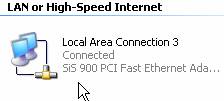
You will need certain equipment, depending on the location:
To install the camera:
To set up and focus the camera
For cabling:
To install the controller:
INSPECT THE SITE BEFORE STARTING THE INSTALLATION:
CAMERA LOCATION:
In practice, a good place for the controller is near to the client’s computer that is taking the inputs from the door sensors.
After all of this has been prepared, then you can start the installation itself.
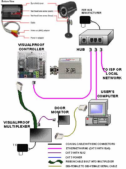
CABLING
Running cable is a straightforward process. You only need to remember that you have to run the video cable AND the power cable for the camera. Do not use a cable tie to join the cable. It will snag as you run the cable. The various components are connected as indicated below:
You can mount the camera base right-side up or upside down. During software setup you can adjust the orientation of the image in the controller software to get right-side up images.
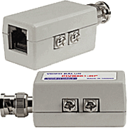
Balun Connector – to connect to Cat#5 cable for the video.
You want to install the camera base 10-20’ from the door entrance. Position it so the camera gets a shot of the customers’ faces if possible. If there is a potential for morning or afternoon glare, move the camera to the side to a 60-90–degree angle from the door.
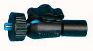
Attach the camera to the swivel.
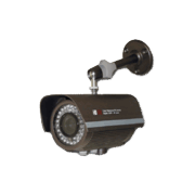
(Assembled camera, ceiling mount)
If the store does not have a hanging ceiling you will have to get creative. The mounting kit includes a plate for mounting on a wall or plaster ceiling.
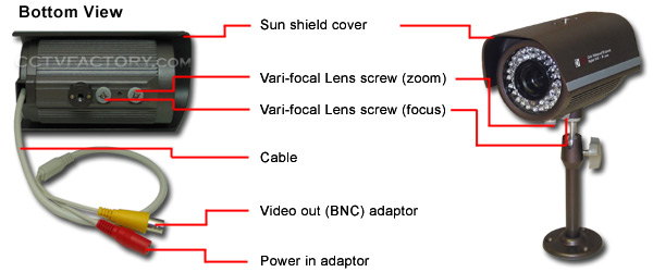
Next, connect the camera power cable. The 12-volt AC connections. On the camera, the wire goes, The other end of the power cable goes to the power supply.
Plug in the power supply to an outlet or extension cord.
In a perfect world, you would have several AC outlets and a network connection at your disposal. In reality, you will probably need the power strip and the hub. You may want to check with the IT department or Internet Service Provider (ISP) to confirm that using a hub will not disrupt the network.
NOTE: you need AC outlets for the controller, camera, VP Multiplexer, and the hub (if it’s used.)
Position the controller so that it has about 2 inches of space around the sides for ventilation. Remember that you do not need a monitor or keyboard for this controller so any convenient shelf space will do, as long as you can reach a source of AC power and a network connection.
Plug in the video cable to the top BNC Balun connector on the back of the controller.
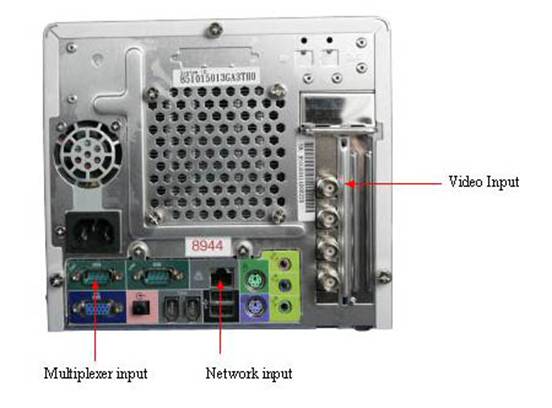
Install the VP Multiplexer.
If you are installing a new door monitor system with Visual Proof, plug the DB-9 connector on the serial cable into the DB-9 connector on the back of the controller closest to the outer edge. Plug the cable from the door monitor into the Visual Proof Multiplexer. Plug the DB-9 cable into the Multiplexer and run it to the DB-9 connector on the back of the client’s PC. Plug the power supply into the power strip. Confirm that the power LED comes on.
If you are installing Visual proof to an existing TRAX door monitor. You need to replace the original MUX with the VP Multiplexer. Plug the DB-9 connector on the Serial cable into the DB-9 connector on the back of the controller closest to the outer edge. Plug the cable from the door monitor into the VP Multiplexer. Plug the cable from the PC that was going to the original MUX to the VP Multiplexer. Discard the original MUX.
If you do not have a network connection available, you can share one with another PC that does have the connection.
Take the existing network cable from the back of the client’s PC and connect it to the hub. Connect a network cable from the hub to the client’s PC. Connect a second network cable from the hub to the controller. Plug the hub’s power supply into the power strip or AC outlet. MAKE SURE YOUR PC CAN STILL ACCESS THE NETWORK.
The easiest way to do this is with a TV (with video input) or LCD monitor that you can see while you are up on the ladder adjusting the camera. Connect the camera to the TV with the short RCA cable from your installation kit. Turn on the TV, set it to the correct video source, and you should see the camera image. If you don’t have a camera image, check the cable connection; make sure the camera has power.
First, loosen both the focus and zoom control lock knobs by turning counter-clockwise until they slide smoothly. Adjust the camera angle and slide the zoom control knob between Wide and Tele several times until you have an approximate image of the customer from about waist-high to the top of the door.
Then twist the button focus to get a rough focus. Again, don’t worry if the image is sideways or upside down. You will adjust that in the controller software later. You may have to adjust the angle, focus and zoom several times to get a good combination. Lock the zoom by tightening the zoom control knob. Do NOT tighten the focus lock knob yet.
Secure the locking ring on the camera mount swivel to lock the camera angle.
HARDWARE TEST:
Plug in the camera power supply. Plug in the VP Multiplexer and make sure it has a power-on LED (red light). Connect the power cable to the controller and plug it into the power strip. You do not have to push the power button on the controller. The power LED and the orange disk drive LED on the controller should light. If it does not, check the power cables to the power strip and make sure the power strip is plugged in and turned on.
When the orange LED is not continuously lit, system has finished booting. (2-3 minutes)
Look at the hub and confirm that it is working. (update this when we have the hub on hand)
SOFTWARE SETUP:
To set up the software, you first have to access the controller through your network. We will give you four ways to access the controller, starting from the easiest.
Every network is slightly different, and there are many subtle variations in Windows operating systems. The object is to find the Visual Proof controller on the network. When this is done, go to SOFTWARE SETUP on page 15
Method #1: The easiest way is to connect a laptop to the network at the hub with a network cable.
To find the Visual Proof controller, click on Neighborhood Network.
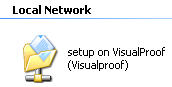
You should find this icon:
If you find this icon, click on it and go to SOFTWARE SETUP on page 15
Method #2: The next-best way is to use a PC that is plugged into the hub.
To find the Visual Proof controller, to click on My Network Places, then Search, then enter “Visualproof” (no spaces) and Enter.
You should find this icon:
If you find this icon, click on it and go to SOFTWARE SETUP on page 15
Method #3:
Your PC’s network workgroup may not match the controller’s. Windows operating systems come with a default workgroup named, appropriately enough, WORKGROUP. This is also the workgroup name of the controller. To access the controller from the PC, you will have to temporarily change the workgroup name to WORKGROUP, then change it back when you are finished.
![]() To
change the workgroup setting:
To
change the workgroup setting:
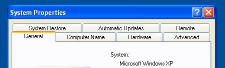
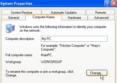
Open the control panel and click on System
You will see a window with several tabs along the top, something like this:
![]()
Click on the Computer Name tab
You should see something like his:
Click on Change
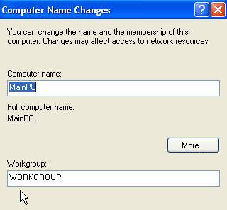
You should see
something like this:
Make a note of the workgroup name. Upper or lower case matters in this situation. Remember, when you have finished the setup of the controller, you need to change your PC’s workgroup back to whatever it was.
Change the Workgroup name to WORKGROUP and click OK, then close out all these windows.
Again, try to find the Visual Proof controller through your Neighborhood Network:
Click on My Network Places,
Then Search, then enter “Visualproof” (no spaces) and Enter.
You should find this icon:
If you find this icon, click on it and go to SOFTWARE SETUP on page 15
Method #4: If neither of the above methods work, then your network most likely uses static IP addresses. The VP controller has a secondary IP address that you can use for the setup process. You will have to go through these steps to access the system.

Open the control panel and double click on Network Connections
Right-click whatever Local Area Network is connected and select Properties
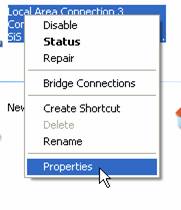
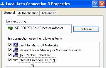
Double click on TCP/IP
You will get something like this:
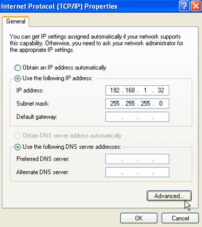
Click on Advanced
You should get something like this:

Click on Add
You should get something like this:

Under IP address fill in 192.168.2.20
Click OK and close your way out.
Open your browser and type in 192.168.2.10
(NOTE: the address you enter in TCP/IP address ends in .20 The address you enter into your browser ends in .10)
SOFTWARE SETUP
Whether you went through neighborhood network, changed the workgroup, or added the IP address, you should ultimately find something like this:
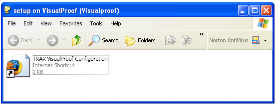
It will have the icon of whatever web browser is your default browser. Double-click on the configuration icon. It will come up in your web browser.
You should see something like

 First,
check the timezone. If you are in a different timezone, click on the drop-down
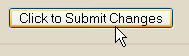
arrow on Time Zone, the select the correct time zone, then click “Click to
Submit Changes”
First,
check the timezone. If you are in a different timezone, click on the drop-down
arrow on Time Zone, the select the correct time zone, then click “Click to
Submit Changes”
\
It may take a few minutes for the Local Time to gray out. This is normal.
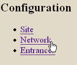
Next, click on Network.
You will see something like this:
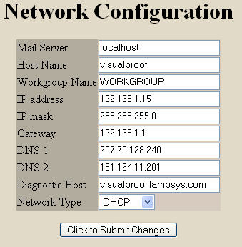
When you are finished, click on “Submit Changes”
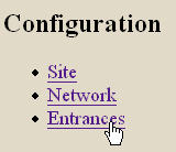
Next, select Entrances:
You should see something like this:
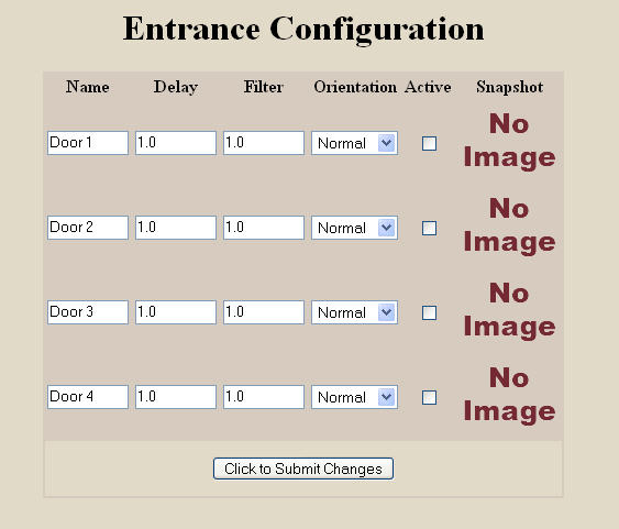
Select the door input that should be active. Door 1 corresponds to the top video input on the back of the controller. Click on “Submit Changes”
You should see the camera image. If you do not have a picture or see a blue screen, see the Troubleshooting section.
If you click on the image under Snapshot you will see an enlarged camera image. It will flicker every few seconds and the time on the bar at the bottom of the image will update. This gives you an ongoing view of what the camera is seeing. When a customer enters and trips the door counter, that image will be saved for future review.
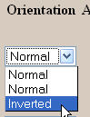
If the image is upside down, change the orientation by clicking the drop-down menu and select “inverted”.
Click
on “Submit Changes”:
You
can customize the name of the door input by typing in whatever name you want.
Avoid using the “/”, “\”, and “.” Symbols. When you have put in the name, click
“Submit Changes”
The “Delay” setting is the time interval from the time the customer breaks the beam of the counter until the picture is taken. In most cases, a 1-2 second interval will give them time to get past the door to get a good image. If you find yourself getting images of the backs of customers, reduce the delay. After any change, click on “Submit Changes”
The “Filter” setting is the timer interval between pictures. This prevents you from getting multiple pictures from a single customer entering the store. It should be set to 1 second in most applications.
After making any changes, click on “Submit Changes”.
If you click on “View Events”,

you will see all the accumulated pictures stored on your controller.
FOR USER MANUAL
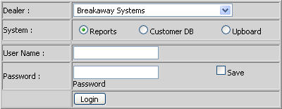
From your internet connection, go to etraxsales.com You will see something like this:

Input your User Name and Password. (These will be emailed to you when your VP system is shipped.) and click on “Login”
 You
will get something like this:
You
will get something like this:
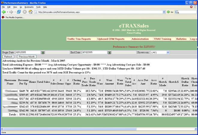
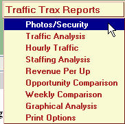
There is a drop-down menu at the Traffic Trax Reports bar:
Select Photos/Security:
You will see something like this:

Enter the date you wish to review and the showroom if you have multiple installations:
You should then see the actual customers who have entered your store on that date:

TROUBLESHOOTING SECTION:
For the problems listed, check each item on the checklist. If all items have been checked and the problem is still present, call tech support.
NO CAMERA IMAGE ON TV DURING CAMERA SETUP
CONTROLLER DOES NOT BOOT.
BLURRED IMAGE AT DIFFERENT TIMES OF THE DAY.
WASHED OUT IMAGE WHEN IN DIRECT SUNLIGHT.
NO PICTURES APPEAR IN CONTROLLER.
If screen is BLUE, no video signal is being received.
If voltage is present at the back of the camera but not at the controller, then there is a problem with the video cable.
Thank you,
If you have any questions, please do not hesitate to call 713 854-7706 or 888 646-5462
Sincerely,
Dave Mink