Visual Proof
Initial Layout and getting prepared before you install. Please read and make
sure you understand the first three paragraphs.
Before
you begin this installation, please call
(713) 466.7177
if you have any questions.
If before or after business hours please call:
Brianda
Cell 832.713.1286
Dave
Cell 713.854.7706
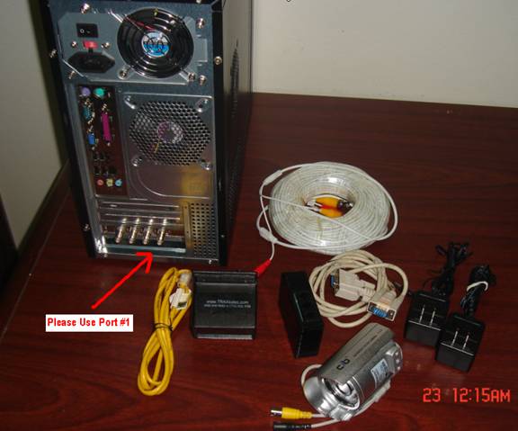
- Place the Visual Proof Controller (TRAX computer) in the
same vicinity as the router. If you are using the customers existing
camera system please place the TRAX Visual Proof Controller next to their
existing DVR.
- Make sure the box is installed horizontally
and the red
and green lights are pointed into the store and the plastic lens is pointing
across the entry towards the reflective material or for wider entrances over
10 feet the included second black box.
- The correct procedure of instillation is as follows.
#1. Connect the Visual Proof Controller to the internet. #2. Call TRAX
(713) 466.7177 and let us verify that the internet connection is solid.
#3. Run the wiring into the ceiling for the camera and traffic counter.
#4. Before mounting the counter on the door frame make sure the system
is connected and you can align the counter with the reflector or reflector
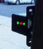
box. #5. After you have aligned the lenses (two solid green lights
and the red light turns off for four seconds when you pass your hand in front
(moving into store) and can hear a beep from the counter, then mount the
counter to the door frame as described below.
- The top of the counter and the top of the reflective
material should be installed at 60 inches to remove counts from small children
running back and forth.) This will put the actual beams at 58 and ½ inches
and catches most adults and insures accuracy.
- The reflective strip is approximately 2 inches by 3 1/2
inches and should be mounted vertically on the door frame so the top of the 2
inch strip is exactly 60 inches high off the floor. Only a 1 inch
diameter circle is required to have solid alignment but we provide the extra
material to insure the best possible beam reflection. If you have extra
material over hanging on the door frame, trim this so it is neatly flush with
the edge and place the additional material on the opposite side of the cut
reflector on the frame.
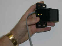
- The traffic counter should be mounted on the hinge side
of the doorframe (if single door entrance) and part of the back of the counter should be exposed so you
can easily adjust the alignment screw (knob on back of counter). Please notice the picture above displays the
counter and is mounted so that part of the device is exposed so you will have
access to the alignment adjusting thumb set screw and the RJ-12 port and can
easily plug in the communication cable. Sometimes a metal door frame has
less than one inch of metal to mount the device and this is fine as long as
you can securely tighten the top and bottom screws through the mounting
bracket into the door frame securing the device. This is a line of
sight device and the only requirement is that the reflector and the counter
maintain clear visibility of one another.
- The wiring should be hidden inside the door frame above
the ceiling (if possible) or through wire mold or conduit, and
run to the provided Visual Proof Controller. Do not run the wire over any lighting
boxes or electrical ballast boxes. And we have found that using push rods for
laying the cable makes this job very easy (these are available at Home Depot
for around 30-40 dollars and are a good investment for any ceiling or cable
running issue.
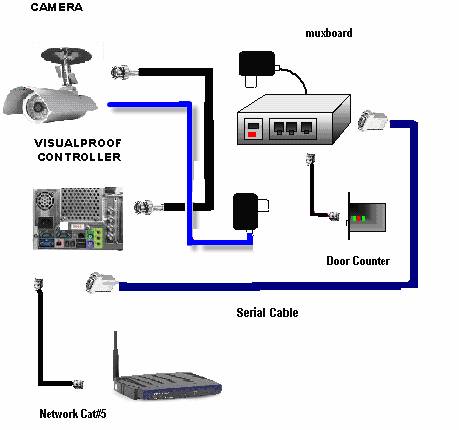
- The traffic Counter connects to the Mux Box then the Mux
Box connects to the VP Controller. We have provided this cable for
plug and play connection. IMPORTANT... do not leave the site until you
have verified that the camera is pointing at the entrance and is viewing
people as they break the beam. Please call 713.466.7177 so we can
connect and verify that all is correctly installed before you leave.
- The counter has a door chime located in the Controller, that only goes off when a customer enters (not when they leave). The
Mux box should be installed at the Controller that is located at the internet
hub, hopefully in the back of the store and not in the sales area. We
have found that if installed in the sales area this will have a greater chance
of failure because sales staff are prone to accidentally unplug the system. The
further from the
sales area the better.
- The Modified CAT5 line (three pair) is then connected with the pre-terminated
RJ-12 connection which plugs into any port on the Mux box (black the size of a
square cell phone).
- This also provides power to the counter at the front
door and a serial connection to the existing customers PC (Standard RS-232
Serial Connection).
- When completed always leave the loop back tester at the store in a TRAX file with the manuals so they can be
referred to in the future. Leave all extra equipment and instruction
manuals with store manager and ask that they save in
a safe and permanent file or location.
- The standard traffic counter (installations at entrances
of 10 feet widths or less will have a reflective tape with a peel off back.
The top of this tape and the top of the counter should be placed at exactly 60
inches from the floor. The 2" reflective tape can be cut so it conforms
to any entrance. IE: an entrance with a one inch step frame at different
levels. A good tip is to not permanently secure the tape until the
counter has been aligned. Use a piece of scotch tape first then peel off
back of tape after you see the red light and two solid green lights and have
heard a beep when you pass your hand in front of the counter.
- If you must install the counter on a wall please know
that you will need to align the counter after the unit is installed. This can
easily be accomplished by shimming the angle to the proper alignment so that
you have two green lights and one red light.
- The system has the ability to have a four second delay
(counts a family of five as one count) or can count each person separately.
Most customers have us program the four second delay before we send the unit.
To test proper alignment after installation is complete hold you hand in front
of the counter so the two green lights go out. Then slowly move your hand
into the store. You will see the green lights flicker back on then the red
light will go off for four seconds then turn back on. You will also hear the
beeper make a short beep. This means that your counter has counted
one entry. The beep can be turned off and let the customer know that the
beeper only goes off when people enter, not when they exit.
- The final test to insure that the counter is perfect is
to #1 place your hand in front of the counter for two seconds (green lights
will turn off. #2. Move your hand slowly into the store (in the
direction of a customer entering). You will notice the green lights
flickering back on then the red light will go off for 4 seconds and turn back
on. You will also hear the beep from the Mux box. Your counter is
now aligned properly and will begin counting customers.
Please call 713-466-7177 or
713-466-4148 if you have any questions.
1.
AC Adapter Output: 7.5 Volt 300mA
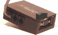
2.
9 Pin Serial Cable 4 ft.
3.
Serial Interface MUX Box. About the size of a cell phone.
4.
Software (installed by TRAX online) before or during installation
5.
125 ft. Modified CAT 5 (three pair) Cable Terminated with RJ-12 (six
wire/three pair) connections
7.
Beam Unit
Included is an accessory packet containing the
following. (Items Not Pictured)
1.
4 #10 x 1 3/16 Screws with Plastic Anchors
2.
1 Allen Wrench 6 - 32
3.
1 Reflective Strip Sticker 2 x 3 1/4
4.
9 Pin Serial Loop Back Tester
Note: The Serial Interface has three
inputs. This device is designed to connect three individual entrances to the
same system. Each port performs the same function and are not beam unit
specific. In a standard one entry configuration the cable may be plugged into
any of the three.
Please
note that the Modified CAT5 line will be completely hidden from view in the door
frame.
#2. The
camera should be installed in the ceiling at a 75-90 degree angle from the front
door and (most importantly) not directly pointing at the front door. This is
important because you do not want to be viewing the sun reflecting off
windshields in the parking lot or sunlight off the concrete in front of the
store outside.
#3.
Please confirm which way customers turn into the store (typically away from the
sales area) and the camera should not be closer than 12-15 feet from the front
door, (you need a full field of view of the entire entryway inside the store)
The camera takes the picture 1.5 seconds after the customer walks in so we can
see the entire family, so make sure you can still catch the really fast
customers walking in at a trot.
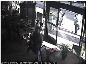
Sample of a poor
installation. This is too close to the door. If the customer goes fast
you will miss them completely. Also there is too much sunlight. This
installation should be back approximately 12-15 feet from the front door and the
camera should be closer to the glass windows and pointing more into the store.
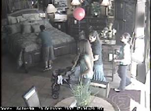
The ideal is a 90 degree profile of the customer. Not a frontal view. If
sunlight is bouncing off a windshield picture will be diluted. A perfect
install is when you can only see the door in the edge of the picture and you can
not see outside the store through the front door at all. The picture is
taken 1 seconds after the customer walks through the beam, so we recommend
that the camera be pointing about 6-8 feet into the store.
Special Note and Camera Location Option...
If you have direct sunlight coming into the store the counter
should be installed so the camera is mounted on the same wall as the doors and
you are capturing an extreme profile. If you are installing in a mall or
location that has no sunlight at the entrance then mount face forward. It
is also important to note that most customers turn right so try to mount the
camera on the right side of the doorway if you have the option. The goal
is to be able to identify if the person walking in is an employee, the mail man
or a new potential customer.
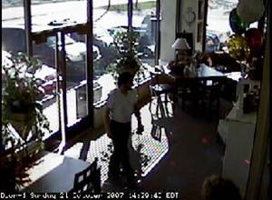
Please note that you can barely see the customer who just
entered on the left.
POOR
INSTALL GOOD INSTALL
(Very dark because pointing at the front door.)
( Same store after correction)
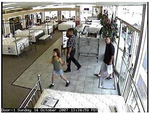
POOR INSTALL
GOOD INSTALL
Too Much back
light Perfect Installation
Visual Proof
installation instructions
SYSTEM REQUIREMENTS
Ethernet connection to the internet
There are 6 steps to install and test the VP system in a
client’s location:
- Install the camera
- Install the controller
- Network connections
- Set up and focus the camera
- System test
INSTALLATION KIT
Each Visual Proof system should be shipped with the
following equipment:
- Visual Proof controller (Proprietary Linux System 80 GB
HD, Dual Core Processor)
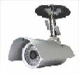
- Camera body (Sony infrared 100' auto focus (best
installed between 12 and 20 feet from front door))
- Camera mounting kit
- Power cable
- Camera power supply
- TRAX Muxboard
You will need certain equipment, depending on the location:
To install the camera:
- Drill
- Phillips screwdriver
- Drywall screws or wall anchors
- Cable ties
- Wire stripper
- Siamese Cable (dual cable with power supply to camera
and Coax for camera transmission)
- Additional RG-59 or RG-6 (In some cables, there is an
aluminum or aluminized Mylar outer conductor. When this is used, be sure to
connect to the copper trace wire)
- Additional BNC connectors for video cables
- Crimping tool for BNC connectors
- Volt meter
To set up and focus the camera
- Portable TV or access to a TV
- Short RCA cable with RCA to BNC adapter
- Neutral-density filter
- Extension cord
For cabling:
- Ladders
- Flashlight
- Throw line (something strong like masons twine)
- Tennis ball or throw weight.
- Electrical tape
- Coat hanger or grabber to retrieve the line.
- Fish tape to pull cable down through walls
To install the controller:
- Power strip
- 5-port network hub or switch
- 3-4 network cables
- 1 crossover cable
- USB to network cable adapter
- Door switch simulator
INSPECT THE SITE BEFORE STARTING THE INSTALLATION:
CAMERA LOCATION:
- Where is the door?
- How high is the ceiling?
- Is it a hanging ceiling?
- Do people come in straight or at an angle?
- If the door faces east or west, how severe is morning or
afternoon sunshine glare?
- Is the camera out of reach of customers or employees?
CONTROLLER LOCATION
In practice, a good place for the controller is near to the
client’s computer that is taking the inputs from the door sensors.
- You do NOT need space for a monitor and keyboard!
- You DO need 2” of ventilation space in back and on both
sides.
- You need an AC outlet.
- You need a connection to the client’s network. If a
cable or connection is not readily available, you can share a connection with
a nearby PC that is connected to the network.
- The cables from the door sensor have to be able to reach
the controller. They will plug into the Modified Multiplexer so that the
signal goes to the controller as well as the counter.
After all of this has been prepared, then you can start the
installation itself.
CABLING
Running cable is a straightforward process. You only need
to remember that you have to run the video cable AND the power cable. The
easiest way is to tape the ends of the two together and run them as a single
cable. Do not use a cable tie to join the two cables.
It will snag as you run the cable. The various components are connected as
indicated below:
CAMERA INSTALLATION
You can mount the camera base right-side up, upside down,
or sideways. In the last few steps you can adjust the orientation of the image
in the controller software to get right-side up images.
AGC – Automatic Gain Control
BNC Connector – to connect to the video cable.
Screw the lens directly to the camera.
You want to install the camera base 10-25’ from the door
entrance. Position it so the camera gets a shot of the customers’ faces if
possible. If there is a potential for morning or afternoon glare, move the
camera to the side to a 60-90–degree angle from the door.
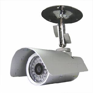
Attach the camera Mounting kit.
Most locations will have ordinary hanging ceilings with
foam ceiling tiles. In these cases you use the strip attachment.
You can use the extension as needed.
(Assembled camera and ceiling mount)
If the store does not have a hanging ceiling you will have
to get creative. The mounting kit includes a plate for mounting on a wall or
plaster ceiling.
Next, connect the camera power cable.
INSTALL THE CONTROLLER
In a perfect world, you will have several AC outlets and a
network connection at your disposal. In reality, you will probably need the
power strip and the hub. You may want to check with the IT department or
Internet Service Provider (ISP) to confirm that using a hub will not disrupt the
network.
Position the controller so that it has about 2 inches of
space around the sides for ventilation. Remember that you do not need a
monitor or keyboard for this controller so any convenient shelf space will do,
as long as you can reach a source of AC power and a network connection.
Plug in the video cable to the top BNC connector on the
back of the controller.
NETWORK CONNECTIONS
GRAPHIC OR PICTURE OF HUB INSTALL
If you do not have a network connection available, you can
share one with another PC that does have the connection.
Take the existing network cable from the back of the
client’s PC and connect it to the hub. Connect a network cable from the hub to
the client’s PC. Connect a second network cable from the hub to the
controller. Plug the hub’s power supply into the power strip or AC outlet.
MAKE SURE THE CLIENT’S PC CAN STILL ACCESS THE NETWORK.
SYSTEM TEST
Hardware:
Plug in the hub and make sure it has a power-on LED. Plug
in the Muxboard and make sure it has a power-on LED. Connect the power cable to
the controller and plug it into the power strip. You do not have to push the
power button on the controller. The power LED and the Red, Blue, orange disk
drive LED on the controller should light. If it does not, check the power
cables to the power strip and make sure the power strip is plugged in and turned
on.
Look at the hub and confirm that it is working. (update
this when we have the hub on hand)
The object is to find the Visual Proof controller on the
network.
The easiest way is to connect a laptop to the network at
the hub with a network cable. The next-best way is to use the client’s PC that
is plugged into the hub.
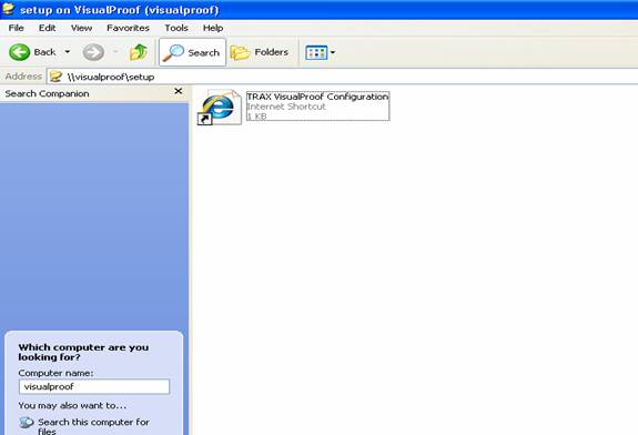
To find the VisualProof controller, to click on My Network
Places,
then Search, then enter “Visualproof” (no spaces) and
Enter.
You should find this icon:
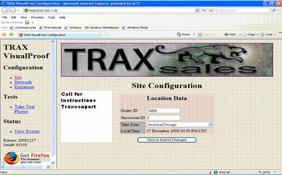
If you cannot find it, you will have call traxsales
713-466-7177, 713-854-7706
Double-click on the VisualProof icon.
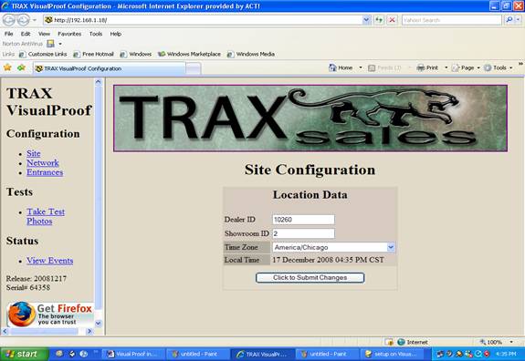
Open the set-up folder:
You should get something like this:
Open the set-up folder . It will come up in your web
browser.
u should see the camera image. Note if the image needs to
be rotated to be right-side up. If you do not have a picture, see the
Troubleshooting section. Close this window.
Click on Site
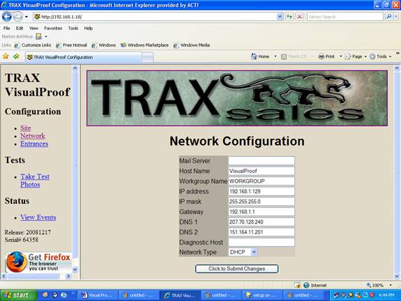
Click on Network this
information is provide to IT
Click on Entrances is ready
Setup
It’s Miller time.
TROUBLESHOOTING SECTION:
For the problems listed, check each item on the checklist.
If all items have been checked and the problem is still present, call tech
support.
NO CAMERA IMAGE
- Check power and video connections.
CONTROLLER DOES NOT BOOT.
- Check power cord connection.
- Check power strip connection.
- Confirm power strip is on.
- Press power button on front of panel.
BLURRED IMAGE AT DIFFERENT TIMES OF THE DAY.
WASHED OUT IMAGE WHEN IN DIRECT SUNLIGHT.
- Reposition camera. Repeat focus procedure.
NO PICTURES APPEAR IN CONTROLLER.
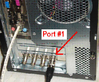
If screen is BLUE, no video signal is being received.
- Check that video cable is plugged into top BNC socket on
the back of the controller is correct Number #1.
.